Tuesday, February 23, 2016

Wisp1_RevA


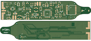
Over the weekend, I completed "Rev A" of my Wisp1 tracker.  I'm calling it "Rev A" on the chance that there are layout or minor errors that may require a minor board spin based on the same basic design.  I've ordered boards through oshpark.com and stencils through oshstencil.com.  I just ordered 3 boards for now.  If there is a design error, I may never build more than one anyway.  If they look good, I'll panelize them, and order through hackvana.com to get the 0.8mm boards with 1oz copper.


I'm recording some notes to myself below.  I bumped into a bunch of minor issues along the way. Hopefully these will save me a bit of googling next time.

Previews and Gerber naming
  • oshpark.com had problems with the drill file preview on the top page.  The drills showed on the board preview, but the drill preview was blank.  Upon recommendation from OSH, changing the drill file suffix from ".drl" to ".xln" resolved the issue.  Unfortunately, I didn't see a way to change this default in the File / Export / NC Drill page.  It'll have to be renamed each time it's created.
Stencils
  • When uploading the stencils to oshstencil.com, I found that the pads for the smallest parts were not coming through on the stencil.
  • If I looked at the preview page in diptrace, it appeared OK
  • Consulting with OSH Stencils, they indicated that the stencils were actually being created badly, and that the preview in Diptrace was not accurately representing what was in the gerber. They directed me to the "Paste Mask Shrink" parameter (File / Export / Gerber).  It was set to 3.937 mils.  They suggested putting it to 0.  Doing so corrected the problem.
    • In subsequent conversations, Alan, who uses Diptrace, suggested Swell 2.5 and Shrink 2.0.  (other settings were default).  By leaving shrink at 0, the paste area may be too large, resulting in too much paste.  We'll see when the boards arrive.
Process for creating Gerbers
  • Configure settings as above.
  • Create a folder to dump the gerbers into.
  • File / Export / Gerber
    • [Export All]
  • File / Export / NC Drill
    • [Auto]
    • [Export All]
    • Rename the "Through.drl" file to "Through.xln"
  • Create an empty .zip file in the Gerbers directory.  
  • Drag all files into the .zip file.
  • This .zip should now be usable by the board houses and stencil makers.
Board ordering notes
  • Preferred boards are 0.8mm with 1 oz copper.  OSH Park can do 0.8mm, but presently only with 2 oz copper.  Hackvana can do the boards as preferred, but they're a bit more manual to order from.
Saturday, February 20, 2016

Wire weight measurements

As I consider my Pico tracker, transmitting on HF frequencies, the weight of the antenna becomes a real factor.  At 30m, we're talking about a dipole that's 46 feet of wire.  Even light wire adds up!

I picked up an assortment of magnet wires to do some comparative measurements.  The data are below.

Wire Sample
Length
(m)
Sample
Weight
(g)
Calculated
Weight
20m dipole
(10.124m)
(g)
Calculated
Weight
30m dipole
(14.123m)
(g)
30ga Wire Wrap
7.062
4.8
6.9
9.6
36ga Magnet
7.062
0.8
1.1
1.6
40ga Magnet
7.062
0.3
0.4
0.6

The 40ga is extremely light.  Here is a comparative photo of the three:


My wife is an expert with textiles.  We're going to try making a very fine 4-ply yarn, with one ply being the 40ga magnet wire.  We'll use this plied fiber between the balloon and tracker for the counterpoise.  

For the antenna, I'm unsure.  The 40ga wire is VERY fine, and tends to bunch up.  In order to keep the antenna element vertical, it might be necessary to put a very small weight at the bottom of the wire.   I'll have to think about that one.

Measuring output power of Adafruit Si5351 board

Since I'm planning to use a Silicon Labs 5351 CMOS Clock Generator to make WSPR signals on my new tracker, I've been doing some testing with an Adafruit Si5351 protoboard.  I can see it generating a reasonable signal, but my Service Monitor (IFR FM/AM-1200S) isn't capable of measuring output power in the milliwatt range.


Unfortunately, the DB numbers in the display are relative, and not actual for low power input like this.  Instead, I tried to make measurements using my oscilloscope.  My scope doesn't have a 50ohm input, so I wired it up through a splitter and attached the ends to my scope probes.


Feeding the output directly into my oscilloscope, I could see that it was on frequency, and generating 2.46v peak-to-peak.


Output power is measured as:   P = Vrms^2 / ohms.  We have 2.46 peak to peak.  Vrms = Vp2p/2 * .707.  So, Vrms = 0.870v.  The Si5351-b outputs at 50 ohm impedance, so P = 0.870v^2 / 50ohm = 15mw.   That's curious, as other Pico tracker builders are reporting an output power in the 20mw range.   It's possible that all the harmonics are accounting for the difference in power.  I'm not sure.


The Adafruit protoboard has it's own LDO regulator, and will operate anywhere between 3.3-5v. During my testing, I was feeding it 3v3.   With my multimeter, I could see it was providing 3.11 volts to the 5351 chip on the board.

My tracker will be running at 2.5v.  Presuming (and that's a big presumption) that the output power will be proportionally diminished, then my board would be making (2.5v / 3.11v) * 15mw = 12mw. That seems pretty low.  I'll want to do more experiments with my own board when I get it together.


Thursday, February 18, 2016

WSPR station at W2CXM

A friend of mine, Jim / N2NXZ, let me know that he was launching a Pico Balloon with a WSPR tracker on it this afternoon.  I had all the pieces necessary to set up WSPR at the W2CXM shack (I'm the club advisor), so I decided to run over at lunch hour and set it up.

We had received a Signalink USB with some Club funds within the last week.  I took it over and set it up with the Kenwood TS-2000 we had in the shack.


The TS-2000 is hooked up to our Butternut HF-9 vertical, atop the center of Barton Hall.


I went ahead and tested it with Ham Radio Deluxe (I had used my personal Signalink with the club TS-2000 previously, so I just wanted to make sure everything was still configured well.  With a few PSK31 receives, and a test transmit, it all looked good to go!

I installed NTP software, configuring it to point to the campus time servers (critical for WSPR), and then installed WSPR software.   I set it up to listen on 30m.  I immediately started getting some data. I went ahead and configured WSPR to uplink the "spots" to the WSPR stream, so that they are available on the internet as "http://wsprnet.org".


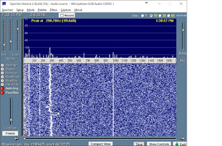
The columns of waterfall data are in 2 minute chunks, with most recent on the right, and oldest on the left.  They represent signals we're receiving within the band reserved for WSPR signals.  I got things pretty much sorted out, and sure enough, I started receiving Jim's balloon!


For a good chunk of his flight across southern New York, W2CXM was the only station receiving him.  I was grateful that I had taken the time to set it up!

I configured the software to transmit "10%" of the time.  That means it should be transmitting W2CXM's information out every 100 minutes or so.  I looked later in the day at the WSPR map. Even transmitting with a mere 5 watts, we were received all over the world!


Every blue square is a station that received us in the 12 hours, or so, that the WSPR station has been running at W2CXM on 30m.  Pretty cool!

I've left WSPR running at W2CXM.  It's a nice addition to the station, and will be helpful as we work on Balloon launches in the future.

Tuesday, February 16, 2016

More WSPR filter planning

Following up on my previous post.  I found another filter planning page - wa4dsy.net.  For this one, I put in data for a Lowpass filter, cutting off at 14MHZ.  It gave some plots of results.  I liked the Chebyshev plot the best.


Note, that the loss at 13.50mhz is only 0.2db.  The other plots showed 0.7.   Comparing the results to the calculatoredge.com page I found they were fairly similar.  Looking at inexpensive components on digi-key, I made the following comparison and decisions:


Calculator Calculatoredge.com wa4dsy.com Plan
14 MHZ


L1
830nH
705nH
1.0uH
C1
299pF
253pF
270pF
C2
299pF
253pF
270pF


All of these components are available in 0603 package, and pretty cheap on DK.

Saturday, February 13, 2016

Signalink mods

So, I read a bit online about modifications to the Tigertronics Signalink.  It turns out there are some well known problems.  I decided to make one of the mods to my own Signalink.

Low End Noise floor

There is a modification to reduce some noise at the low end of the frequency range.  Basically, the power coming in from the USB port has a fair bit of noise that gets inserted between 0-100 hertz in the spectrum.  This modification draws power, instead, from a 3.7v internal source which manages to filter out some of the noise.

Spectrum Before the Mod
You can see a good bit of noise at the low end of the spectrum.

Spectrum After the Mod
After the modification, the noise is significantly lower between 0-100 hertz.  Unfortunately, the bogey at 300 hertz is a little better defined.

Unmodified Signalink

On the upper right, just below the second pot, I've circled the voltage divider we're going to modify.  It's a 1K / 1K voltage divider, cutting 5.0v into 2.5v.

Modified Signalink


The modification is shown above.   The PIC processor is fed with 3.75v.  There must be a regulator somewhere that's converting 5.0v to 3.75v.  A side effect is that the regulator apparently dampens the noise that we're trying to get rid of.  So, this patch wire takes 3.75v up to the voltage divider.  I removed the 1k resistor connecting to the 5.0v power source, and inserted a 510 ohm resistor (inside the shrink wrap on the wire).  This yields 2.48 volts.  Close enough for government work.  The result is illustrated above in the spectrum.

Further work

I'd like to clear up that bogey at 300 hertz.  Not sure how exactly to do it.

Also, the SignaLinkUSB Mods link shows quite serious issues resulting from the transformers.  He replaced the transformers to good effect.   I put a noise source into my signalink, and did NOT see any variation in the noise floor, as shown in the link above.  I would like to look further into that problem when I get some time.

WSPR tracker output filters

Thinking about filters

I'm in the midst of designing a small WSPR tracker based on SMD technology for use with Pico Balloons.  I hope to attempt a circumnavigation with my design and home built envelope.

My tracker will be using a Silicon labs Si5351 CMOS clock generator.  Per the datasheet, the clock generator is spec'd to an 50 ohm output impedance.   Note, that there are different Si5351 parts. The "-B" parts seem to be the ones you can find now, and they have 50 ohm termination.  The earlier non-"-B" parts, were rated at 85 ohm.


Looking at the output of an Adafruit Si5351 protoboard on a spectrum analyzer, the output signal would definitely benefit from some filtering.There are some sizable harmonics.


First pass at a filter plan

I'm new to RF design, but as I understand it, I should probably have a DC Coupling Capacitor as well as a filter network.  I'm going to begin with a simple Pi Lowpass filter and see how that goes.


In this design, C22 is the coupling cap, and the Pi filter is comprised of C2, C5 and L3.

Coupling Cap

The target output frequency is on 30m, at about 10.1 Mhz.  I found the following gem on the interwebz, so it must be true:
You generally want the capacitor reactance (impedance) to be much less than the circuit impedance.
The reactance of a capacitor is Xc = 1/(2*pi*f*C) where f is the frequency of operation.
Thus the higher the frequency and the larger the capacitor, the smaller the reactance.
Thus for a typical 50Ω circuit impedance, you probably should have the capacitive impedance no more that about 1% of 50Ω or 0.5Ω.
So, for example, at 2.4GHz frequency, the capacitor should be no smaller than C = 1/(2*pi*2.4GHz*0.5Ω) = 132pF.
Substituting in 10.1Mhz into the formula, I get a value of 31.5nf.

Filter values

 I found a Chebyshev Pi LC Low Pass Filter Calculator on the web.  I plugged in values as documented below:


Unanswered questions 

I'm not an RF guy, so I have no idea if I've done any of this correctly.  In particular, I have these questions:
  1. I put the cutoff at 11 Mhz, since WSPR is very low bandwidth.  Is that too aggressive?
    1. Answer: Probably.  I'm rethinking using 20m rather than 30m for flight.
  2. Is the coupling cap in the right place?  Should it be after the Pi filter?
    1. Answer: Yes, according to a colleague who is an RF engineer.

I'll update this into more of a "This is what I did" document as I finalize my design.