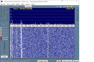
Low End Noise floor
There is a modification to reduce some noise at the low end of the frequency range. Basically, the power coming in from the USB port has a fair bit of noise that gets inserted between 0-100 hertz in the spectrum. This modification draws power, instead, from a 3.7v internal source which manages to filter out some of the noise.
Spectrum Before the Mod
Spectrum After the Mod
Unmodified Signalink
Modified Signalink
The modification is shown above. The PIC processor is fed with 3.75v. There must be a regulator somewhere that's converting 5.0v to 3.75v. A side effect is that the regulator apparently dampens the noise that we're trying to get rid of. So, this patch wire takes 3.75v up to the voltage divider. I removed the 1k resistor connecting to the 5.0v power source, and inserted a 510 ohm resistor (inside the shrink wrap on the wire). This yields 2.48 volts. Close enough for government work. The result is illustrated above in the spectrum.
Further work
I'd like to clear up that bogey at 300 hertz. Not sure how exactly to do it.
Also, the SignaLinkUSB Mods link shows quite serious issues resulting from the transformers. He replaced the transformers to good effect. I put a noise source into my signalink, and did NOT see any variation in the noise floor, as shown in the link above. I would like to look further into that problem when I get some time.


No comments:
Post a Comment