Friday, September 9, 2016

HAL_FLASHEx_DATAEEPROM_Program() bug

HAL_FLASHEx_DATAEEPROM_Program() bug

The Bug


I've been using HAL drivers to program an STM32L151CB chip.  While trying to use the HAL_FLASHEx_DATAEEPROM_Program() function in the STM HAL library, I discovered that when I wrote a data byte, and then a "0" into the next byte, that my data was lost.  I wrote a sample program, source below, which demonstrated the problem.

The Fix


It turns out that I was using the STM32L1xx_HAL_Driver V1.1.2 that came packaged with the STM32CubeMX 1.4 code.  After determining that this was a bug in the HAL driver, I thought to check, and there was a newer STM32CubeMX 1.6 release, which included STM32L1xx_HAL_Driver V1.2.0.  The new code worked beautifully.   I did find a mention of a fix in the release notes for driver version 1.1.3, but it was quite vague:


  • FLASH:
    • Correct issue preventing Cat.1 devices to write data in EEPROM.


Sample code


void
DemoFlashBug(void)
{

 HAL_StatusTypeDef status;
 uint32_t Byte0Addr,Byte1Addr;

 HAL_FLASHEx_DATAEEPROM_Unlock();  //Unprotect the EEPROM to allow writing

 Byte0Addr = 0x08080000;
 Byte1Addr = 0x08080001;

 // Print values before we do anything
 trace_puts("Prior to updates");
 trace_printf("Byte0 is: %d\n", *(uint8_t *) Byte0Addr);
 trace_printf("Byte1 is: %d\n", *(uint8_t *) Byte1Addr);

 // Set the first byte to 99
 status = HAL_FLASHEx_DATAEEPROM_Program(TYPEPROGRAMDATA_BYTE, Byte0Addr, (uint32_t) 99);
 if (status != HAL_OK) {
  Error_Handler();
 }
 // Print values after setting byte 0
 trace_puts("\nByte 0 should be set to 99");
 trace_printf("Byte0 is: %d\n", *(uint8_t *) Byte0Addr);
 trace_printf("Byte1 is: %d\n", *(uint8_t *) Byte1Addr);

 status = HAL_FLASHEx_DATAEEPROM_Program(TYPEPROGRAMDATA_BYTE, Byte1Addr, (uint32_t) 0);
 if (status != HAL_OK) {
  Error_Handler();
 }
 // Print values after setting byte 1
 trace_puts("\nByte 1 set to 0");
 trace_printf("Byte0 is: %d\n",  *(uint8_t *) Byte0Addr);
 trace_printf("Byte1 is: %d\n", *(uint8_t *) Byte1Addr);

 if ( *(uint8_t *) Byte0Addr != 99) {
  trace_puts("WTF?!?\n");
 } else {
  trace_puts("OK, it worked!\n");
 }
 HAL_FLASHEx_DATAEEPROM_Lock();  //Unprotect the EEPROM to allow writing

}

Moral of the story

Grab the latest HAL drivers.

Tuesday, September 6, 2016

Secondary Telemetry Packet

Secondary Telemetry Packet


I've decided I want to report more data, though the additional data does not need to be transmitted with each transmit sequence. Instead, I'llo initially send it once per hour.

The second telemetry packet will follow the other two packets on an hourly basis. The encoding is described below. The encoding of the first two packets were blogged previously.


Third Packet
The third telemetry packet will encode data that is stashed in non-volatile memory on the tracker.  It will give performance metrics of the tracker itself.  It is distinguished from the normal telemetry packet in two ways.  First, it will begin 4 minutes after the primary (callsign) packet, rather than two. Second, it will use an value in the DBM field which is unused in a normal telemetry packet.  That will immediately flag that this is a secondary telemetry packet.

We'll illustrate the encoding scheme by decoding an example.

     QC1BAD FN12 60

The callsign consists of 6 positions with potential values as follows:

Position Possible Values Use in Scheme (number of values) Number of Used Values /
Number of Possible Values
Callsign 1 Q,0 Telemetry Channel (2) 2 / 2
Callsign 2 0-9,A-Z Transmit cycles -modulo 36 (36) 36 / 36
Callsign 3 0-9Telemetry Channel (10) 10 / 10
Callsign 4 A-Z Boot Ups - modulo 26 (26) 26 / 26
Callsign 5 A-Z Watchdog Resets - modulo 26 (26) 26 / 26
Callsign 6 A-Z, space GPS Resets - modulo 27 (27) 27 / 27
Gridsquare 1 A-RSame as Packet 1 n/a
Gridsquare 2 A-R Same as Packet 1 n/a
Gridsquare 30-9 Same as Packet 1 n/a
Gridsquare 4 0-9 Same as Packet 1 n/a
DBM 0-18 18 (hard coded to 60 dbm) 19/19

Callsign Positions 1 & 3: Telemetry "Flight" or "Channel" number

Positions 1 & 3 allow for 2*10 = 20 possible values.  This allows for up to 20 pico flights to be in operation simultaneously without telemetry confusion, provided everyone cooperates and uses a unique pair of characters in those two positions.  In the example above, the two telemetry channel bytes are "Q" and "1". We can interpret a "Q" in position 1 as the 10's value, so this is "Flight Number 11" or "Channel 11".

Transmit Cycles

We count each time the tracker does a transmit sequence (2 or 3 per sequence).  This field wraps at 36.  Since we send the count hourly (6 cycles), we should wrap each 6 hours of daylight operations, but we should be able to tell that it happened from the hourly telemetry.  This will be helpful in the event of tracker reboots or lost packets.

Boot Ups


We count each time the tracker boots up, at power on.  Theoretically this happens once per day, but it appears the tracker browns out in the morning and at night.  The BootUps counter will help give a better picture of that scenario for consideration of future enhancements.  These are counted modulo 26.

Watchdog Resets


We count each time the tracker hangs, and the watchdog timer reboots it.  In an ideal world, this counter will never increment.  Uh huh.  It'll be nice to know, though!  These will be counted modulo 26.

GPS Resets


The GPS presently will go through a pretty hard reset if it is unable to get a lock for 5 minutes straight.  We'll count those here.  They are counted modulo 27.

Example

     QC1BAD FN12 60

Q = Telemetry Flight ID10's place
C = 12 transmit cycles
1 = Telemetry Flight ID 1's place  - Q,1 = Flight 11.
B = 1 boot up.
A = 0 watchdog resets
D = 3 GPS resets


Friday, August 26, 2016

Flight wisp1c_9

Flight wisp1c_9

Planned changes

  • Two 36" Qualatex envelopes.  Stretched with air, this time, for two days at 0.4 psi and then emptied and refilled with Helium.
  • Transmit frequencies: 20 meter band only.  10 minute intervals.
  • Gatewayed to APRS at kd2eat-8.
  • Counterpoise is taped at 30" intervals to 15 pound test braided fishing line.  The antenna is not braided to string this time.
  • Installed a small swivel on the end of the counterpoise so that it could be snapped to the balloon.  This made testing and transport easier, as I didn't need to deal with the balloons as much.
  • A small patch at the far end of the antenna and counterpoise is stripped to allow for continuity testing, since I've been having antenna problems.

Preparation


I didn't take a lot of assembly pictures for this one.  This is the 9th board (third board of the third panel).  Pictures of previous board assemblies are in previous flight blogs.  

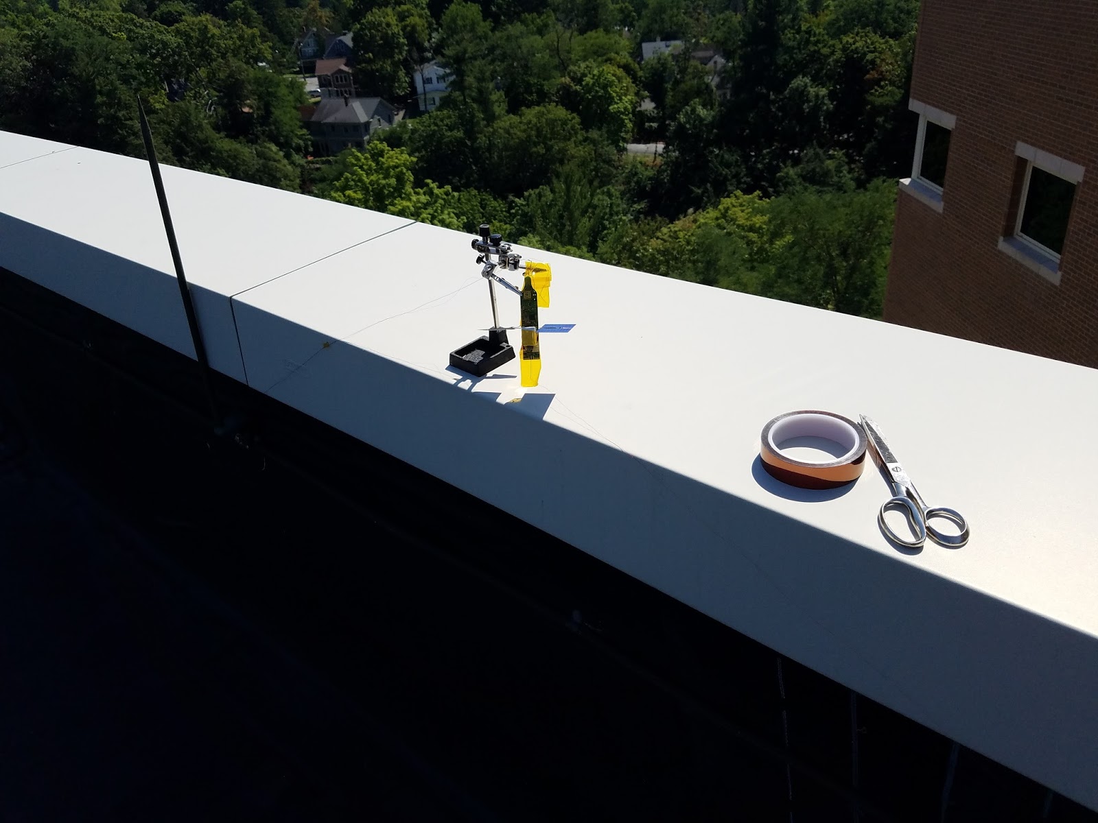
Here's the finished tracker sitting in the sun for a test transmit the day before launch.  

The signal was nice and strong across the road at W2CXM.  The antenna was just laying across the roof of this building horizontally, so this isn't bad, given that it's only transmitting at about 10mW,


Here's the initial flight prediction.  We'll see how it goes!


Day 1

I had to finish balloon preparation at home and take them into the office to attach to the tracker.  As it's the weekend, and my Wife and I are NOT morning people, this means that I got to the office about 2pm. hehe.  Here's the final test on the roof prior to launch.  I used just an inch or so of Kapton tape over the swivel, after securing the balloons, just to make sure that the swivel didn't poke anything, and that there would be a little less friction with the string and swivel sliding around.


And they're off.  It was a very calm day, and the balloons just lifted straight up and away from me.  Good thing, as I was launching alone, and it would have been tough if I was fighting a breeze!


Here's the waterfall, once it was in the air.  Nice and strong, now that it's vertically polarized and away from the building.


Final results for Day 1

The balloon stabilized about 8,222 meters as the sun was going down.   That's lower than I would have hoped, but it beaconed there 3 or 4 times before the sun set.  We ended the day in grid square FN22xk, having covered 123 miles.   It didn't cover a lot of ground, averaging about 24 mph for much of the flight.   The weather was still clear over New York, so I was optimistic I would see the balloon again in the morning.

Day 2

We awoke in grid square FN51dh, having covered 236 miles overnight.  The tracker performed very well throughout the day, though progress remained slow.  We ended the day in grid square FN80fq, having covered 324 miles in daylight, averaging 29 mph.


Day 3 - end of flight

We awoke in grid square GM18nd having covered 398 miles overnight.  The altitude seemed normal at 8,222 meters.  We climbed to 8,333 meters and held there for about a half hour.  Unfortunately, shortly after that, we began a rapid descent.   Within 100 minutes, we fell below 777 meters and lost contact.  That's a rate of about 1.25 m/sec.  Within about 37 miles from our first spot of the day, we were in the water.

At launch, with a free lift of 5g, we had an ascent of about 1 m/sec.  If an envelope had failed completely, we would have had about 37g of dead weight added to the weight of the payload being carried by a single balloon, with 2.5g of free lift.  I think it would have fallen much faster than 1.25 m/sec if we had an envelope failure.  We probably would also have have seen acceleration in the descent.  We really didn't.  It was a relatively steady descent.  I'm guessing it was moisture on the envelopes.


We were just approaching the edge of "Tropical Depression Nine".  I suspect we hit it.  The satellite imagery here might have been a little out of date.  The weather was moving northward.


Daily Statistics


Day Rcvd
Pkts
Lost Pkts Percent
Rcvd
Late GPS locks GPS Resets Watch
dog Resets
Farthest Rcv Station (miles) Average stations / beacon Max stations / beaconDaylight Dist
covered
(miles)
Avg MPH
1
56
0
100
1
0
0
3826
7.3
10
123
27
2
118
0
100
10
0
0
3615
9.3
17
324
29
3
26
0
100
4
0
0
3226
7.4
12
37
13


Observations


  1. The new antenna design worked very well, and was actually lighter, while using heavier braided fishing line.  I'll stick with it.
  2. Stretching the balloons with compressed air may have left condensation inside the envelopes. That would explain the reduced altitude.


Flight wisp1c_8

Flight wisp1c_8


Summary:  

Train wreck.

Changes this flight


  • Two Qualatex balloons
  • Modified code to hard code the LSI (internal) oscillator, since the external wasn't working.
  • Added calibration code for the LSI.  The "Synchprediv" for the RTC is set appropriately based on the measured speed.

First failure

I could never get the external Low Speed Oscillator to work properly.  I hard-coded the software to use the internal oscillator.  This was a worthwhile mod to do, in any event.

Second failure

I put the tracker up on the roof to beacon for an hour during a meeting.  The balloons broke free of the things holding them down, due to a gust of wind.  They yanked the tracker off a ledge causing the solar panels to shatter on the roof.  The balloons then broke away and were lost.

Third failure

While stretching a new pair of balloons, I accidentally ruptured a balloon while disconnecting it.

Final failure

With the tracker reassembled, we went to launch it on the roof again.  It was a gusty day.  The balloons ended up tangling on a ledge high above us.  By the time we got them untangled, apparently the antenna was broken.   Though the tracker was still blinking lights and functioning, it was not being heard.  In my rush to get it in the air, and get back to work, I didn't re-test it prior to release. The tracker sailed off, and was never heard from again.

All in all, it was a relief.  That tracker was cursed!

Tuesday, August 9, 2016

Stretching 36" Qualatex balloons

Stretching 36" Qualatex balloons


Issue

In flight, the 36" Qualatex balloons will stretch over the first few days.  In order to maximize altitude, conventional wisdom is to stretch them prior to flight at a pressure a little higher than they will ever see.  That way, the balloon will climb to maximum altitude right away.  Also, pre-stretching may catch any defects in the balloon prior to flight.

The Numbers

In flight, the balloon will experience about 0.2 - 0.3psi.  A few other pico flyers are pre-stretching to 0.4psi.

Filling rig

My filling rig is shown here, along with one of the fill nozzles I put in the balloon.  Starting at the top, the first valve goes to my helium tank.  The second and fourth (bottom) valve lead to balloons fill lines.  The third one is a short line that goes to my manometer.

I'm holding one of my fill stems here.  The rigid plastic fill stem is actually stolen from a can of Great Stuff Insulating Foam.  It fits neatly into the 1/4" vinyl hose.  The red tape is Silicone Self-fusing adhesive tape.  It provides  a somewhat spongy surface to help seal around the balloon fill hole.


I'm using hose pinch-clamps as show below.


Here's a pinch clamp on the hose, prior to insertion in the balloon.


I inserted the fill line deeply into the valve, so only a little of the silicone tape was showing.


I roll the excess balloon film around, and slide the hose clamp into place.


The gold balloon was just for practice.  The two silver balloons are being stretched in preparation for the next flight.  With two balloons on the filling rig, I can alternate back and forth as I fill and stretch.  Once filled to 0.4 psi, the balloon will stretch and the pressure will gradually go down.  While that's happening, I switch over to the other balloon, by simply turning a few valves, and top up the other balloon.  I'll alternate back and forth for a day or two until they seem stable.


Here's my manometer.  If you look carefully at the valves, you'll see that nothing is open except the manometer at the moment, so the fill rig is pressurized to 0.435 psi.


Results


The rig works pretty well.  I think I have a few tiny leaks, but I can easily get a balloon up to 0.4 psi and I can see it stretching nicely.  While I would like it to be completely leak-free, as my friend Kevin / WB2EMS says, "Good enough is the enemy of better."

Wednesday, August 3, 2016

Flight wisp1c_7

Flight wisp1c_7

Planned changes


  • Using a custom envelope provided by Jim / N2NXZ, rather than a pair of 36" mylars.
  • Second flight using new, more rectangular, solar panels.  Used a little crazy-glue after soldering to reinforce the connections.
  • Modified the board voltage to 2.96 volts.  See previous post, yielding 11.4 mw of output power.
  • Modified voltage divider for Solar charger to make 4.6 volts.  Testing showed it making 5.02v, which exceeds the rating of the supercap.
  • Improved braiding of the dipole wires (practice makes perfect).
  • More careful measurement of both dipole elements to 209.4 inches.
  • Code modified to use DMA rather than polling for DMA calculations. 
  • Transmit frequencies: 20m only.  6m intervals.
  • Gatewayed to APRS at kd2eat-7.

Assembly


Building the boards:


Braiding the dipole wires with 2 strands of thread:


Tracker run through its testing, and the antenna built.


Setting up a dummy weight on a clip for balancing the balloon.  14.2g tracker + 5g free lift = 19.2g.


Tracker and dummy load:


Balloon balanced to 19.2g, sealed, and attached to the tracker.  All set for flight:


Envelope calculations

I stretched the envelope at 0.4psi to assure it could take the pressure.  It seemed to hold up fine, though my pressure testing rig still has some leaks, so I could not maintain it at pressure for exhaustive testing.  I removed the fill nozzle and quickly sealed the envelope, still under some pressure.  I then hung weights on it until I achieved neutral buoyancy.  I used this weight, and the known lift of helium to estimate the volume of the envelope at 0.270 cubic meters.  Unfortunately, I misplaced the numbers for that, though I had the final result recorded.  For the record, this envelope measured 37" x 51".  The seams were heat sealed and reinforced with mylar tape.

Float calculation

Using the standard float spreadsheet, I put in the following parameters:

Gas: Helium
Envelope volume: 0.270 cu meters
Envelope mass: 78.9g
Payload mass: 14.4g

Calculating at 5.0g of free lift, it resulted in an estimated float height of 10,190 meters.

Prediction

I'm planning launch for Thursday morning, August 3, 2016.  The predicted flight path is below.


Day 1

Well, the flight lasted 4 hours and 30 minutes.  After seeming stable for more than an hour at between 9,111 and 9,333 meters, the envelope sprung a leak and descended, landing not far from Poughkeepsie, New York.


Analysis

There were 720 reports of the primary telemetry packet, meaning an average of 11 reporting stations per packet. One transmission was reported by 17 WSPR stations. The farthest station was 3294 kilometers away, in Spokane, Washington. I'm really satisfied with the antenna and transmitter performance this time out.   The waterfall, shortly after launch, was very strong.


Next Steps

Speaking with Jim / N2NXZ, we think the mylar material we're using may have some cold sensitivity.  We're going to try some experiments on the ground to pressurize an envelope in a cold environment to see if we can reproduce any issues.


Messing with output power - higher VCC

Messing with output power - higher VCC


So, tonight I decided to see if I could increase my output power by increasing the VCC of the board. By default, the Wisp1 is configured for VCC at 2.56 volts.  This generates an output signal at 1.9v Peak-2-Peak, or 9.02 milliwatts.

Now, in practice, there's no technical reason my board can't run at 3v3.  All of the components are certified up to 3.6 volts.

Poking around my parts box, I didn't have the correct resistors to modify the voltage divider for 3v3. However, I was able to boost it up from 2.56 to 2.98 volts.

Almost everything on my board is certified at 2.98 volts, with the exception of the Si5351 chip.  From the datasheet:


Technically, according to this table, the Si5351 requires 3.0 - 3.6v.  However, if you look at the note below, it says "+/- 10%".  By that metric, it would require 2.97 - 3.63 volts.   Well, it never hurts to try!

I swapped the resistors and took a peek.  Sure enough, it was making signal at a higher peak-to-peak voltage.

The p2p voltage is 2.14 volts, which translates to 11.4 milliwatts.  That's a 25% improvement.  I'll take it!

I'll run the next flight with this modified voltage divider.  I still run some risk as I'm out of spec, and these tests were run at room temperature.  However, nothing ventured, nothing gained!